



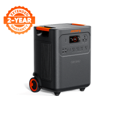
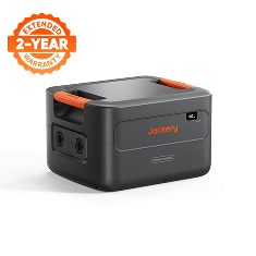




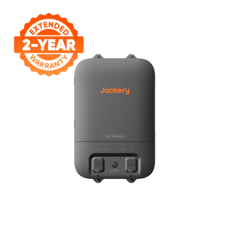
![[Add-on] Jackery SolarSaga 500 X - Jackery](http://www.jackery.com/cdn/shop/files/add-on-jackery-solarsaga-500-x-1493607.webp?v=1786503068&width=324)
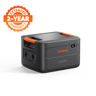
![[Add-on] Jackery Battery Pack 5000 Plus - Jackery](http://www.jackery.com/cdn/shop/files/add-on-jackery-battery-pack-5000-plus-6713401.webp?v=1786503068&width=324)






What Is the Difference Between a Contactor-Based and MOSFET-Based BMS?
Contactor vs MOSFET BMS designs differ mainly in how they interrupt battery current: a contactor uses controlled mechanical contacts, while MOSFETs use electronically controlled semiconductor switches. A contactor-based design may be the better fit when physical separation and controlled connection behavior are central. A MOSFET-based design may fit when compact electronic switching and its applicable electrical and thermal limits suit the system. Neither label determines the right purchase; ratings, protection behavior, and installation requirements do.
Choose a contactor vs MOSFET BMS based on system priorities
Start with the system requirements, not the architecture label. Consider a contactor-based design when the system needs a physical break in the battery path and controlled connection behavior. Consider a MOSFET-based design when semiconductor switching fits the design and its applicable limits are documented.
The switching-method distinction is only a starting point. Before comparing products, list the intended loads, startup behavior, runtime target, charging sources, placement, portability, expansion plans, and installation type. LiFePO4 identifies the cell chemistry, not the BMS switch architecture, so a chemistry or BMS label alone does not establish whether a product fits.

What a BMS does before it switches battery current
A BMS does more than interrupt current. It typically combines cell and pack monitoring with protection and control functions related to voltage, current, temperature, and balancing. The BMS monitoring, protection, and balancing functions described by Texas Instruments illustrate this broader role.
BMS control logic may limit or interrupt a charge or discharge path, but the switch type does not determine battery capacity, runtime, inverter output, charger behavior, transfer performance, or installation requirements. When reading specifications, keep BMS functions separate from the chemistry, inverter, charger, enclosure, controls, and installation details.
How a contactor-based BMS connects and isolates the battery path
A contactor is an electrically controlled electromechanical switch in the main power path. When open, it may create physical separation in that path, but the resulting isolation and fault behavior depend on the complete arrangement, ratings, status diagnosis, and control system.
The TI contactor guidance discusses requirements such as contactor status and isolation behavior. In systems with substantial downstream capacitance, a precharge circuit or sequence may be used before the main contactor closes. TI's precharge explanation describes how precharge can limit inrush into downstream capacitance; the word “contactor” alone does not show that a product includes this feature.
For buyers, the important specifications include contactor ratings, status feedback, isolation or insulation monitoring where relevant, connection sequence, precharge provisions, and fault response. These details show how the mechanical switch participates in the system, but they do not independently establish battery current capability, charging behavior, or inverter performance. Do not manually operate or bypass a contactor-based BMS. Use the manufacturer's approved service process for any required intervention.

How a MOSFET-based BMS controls battery current electronically
A MOSFET-based BMS uses semiconductor switches to control the current path electronically. That category label does not guarantee a particular switching speed, efficiency, heat level, current capability, or reliability; those outcomes depend on the implementation.
Relevant details include on-resistance, device count and arrangement, body-diode paths, gate drive, current sensing, protection circuitry, and thermal paths. For implementation context, Texas Instruments' MOSFET application note explains how device arrangement, sensing, gate drive, and thermal paths can affect voltage drop and heat. In some disabled states, current can travel through body-diode paths, so the product's specified behavior matters more than the MOSFET label.
Look for applicable charge and discharge limits, temperature conditions, protection behavior, and thermal-management information. If those limits are not provided for the configuration, “MOSFET BMS” is not enough to predict performance. The semiconductor stage is also separate from cell monitoring, balancing, the charger, inverter, enclosure, and installation design.
Compare the tradeoffs that can change the architecture choice
These are design tendencies, not rankings. The technical comparison of MOSFETs and contactors covers moving contacts, resistance, wear, welding, feedback, thermal management, and precharge, while TI's technical documentation addresses implementation details that affect the result.
| Design consideration | Contactor-based BMS | MOSFET-based BMS |
|---|---|---|
| Switching method | Electrically controlled mechanical contacts connect or disconnect the power circuit. | Electronically controlled semiconductor devices manage the current path. |
| Open-state isolation | An open contactor may create physical separation, subject to the arrangement, ratings, and diagnostics. | Isolation depends on the device arrangement and the rest of the power-path design; the label does not answer it. |
| Current-path design | Contacts, conductors, coil control, feedback, and any precharge path all matter. | Device resistance, parallel arrangement, body-diode paths, gate drive, sensing, and thermal paths all matter. |
| Repeated operation and response | Mechanical operation, contact wear, status feedback, and connection sequencing may affect the design. | No moving contacts are involved, but electrical response and fault behavior depend on the drive, sensing, protection, and thermal design. |
| Conduction loss and heat | Contact resistance, current, coil control, and enclosure thermal conditions need review. | On-resistance, device arrangement, current, body-diode conduction, and heat removal need review. Neither label guarantees lower losses. |
| Control and service | Review contact status, possible contact wear or welding, control requirements, and approved service procedures. | Review fault detection, thermal limits, device arrangement, control requirements, and approved service procedures. |
Use the table to identify the product details that matter for your system. It does not replace the applicable voltage, current, temperature, protection, connection, and installation information.
Apply the comparison to LiFePO4, portable power, and home backup
LiFePO4 chemistry, BMS architecture, and complete-product performance are separate layers. The chemistry does not require a contactor or MOSFET design, and neither switch type proves that a battery or power station fits a particular installation.
For compact portable power equipment
Assess the complete unit's intended loads, startup behavior, charging and discharging limits, temperature range, thermal management, standby behavior, enclosure, controls, and service path. Compact packaging or a LiFePO4 label does not identify the BMS design. The relevant question is how the BMS limits interact with the charger, inverter, temperature conditions, and user controls.
For home backup and higher-power systems
Pay closer attention to isolation, current-path design, precharge or transfer behavior, thermal management, expansion, service, and installation requirements. Evaluate the battery, inverter, charger, transfer equipment, enclosure, controls, and installation method as one system rather than choosing based on output wattage alone. After defining your loads and installation needs, the Home Backup Power collection can serve as a navigation path, not evidence of any particular BMS architecture.
Before applying either path, record the intended loads, startup behavior, runtime target, charging sources, placement, portability, expansion plans, and installation type. If the system will connect to home circuits, expand, or supply equipment with demanding startup behavior, prioritize the configuration's installation, transfer, expansion, and current-rating information.
FAQ: contactor vs MOSFET BMS
The most useful follow-up questions concern what the architecture label can tell you and which product details should guide the purchase.
What is the main difference between a contactor-based BMS and a MOSFET-based BMS?
A contactor-based BMS uses a controlled mechanical switch in the main current path, while a MOSFET-based BMS uses electronically controlled semiconductor switches. If physical separation is a deciding requirement, request the product's open-state and isolation information first; otherwise, compare the complete current path and protection limits.
Does a MOSFET BMS switch battery current faster or more efficiently than a contactor BMS?
Not automatically. Speed, efficiency, heat, and response are product-level attributes that depend on the electrical arrangement, gate drive, thermal design, sensing, and protection circuitry. Compare the applicable limits under the intended temperature and load conditions instead of choosing based on the label.
Should I choose a contactor or MOSFET BMS for a LiFePO4 home-backup battery?
Begin with the installation path: a system connected to home circuits needs its transfer, isolation, inrush or precharge, expansion, thermal, and installation details reviewed together. LiFePO4 does not select the switch type, so choose between architectures only after the configuration covers those requirements.
Verify the complete product before you choose
Use this five-step process with the model, configuration, intended loads, and installation plan. The BQ76952 documentation illustrates the type of monitoring, protection, temperature, current, and balancing information a buyer may need; the manufacturer's current product documentation controls the final limits.
- Define the application. List the loads, startup behavior, runtime target, charging sources, placement, portability, expansion plans, and installation type before comparing BMS labels.
- Match the exact electrical ratings. Compare the product's voltage, capacity, continuous and peak charge and discharge ratings, inverter output, and temperature limits with the intended requirements.
- Review BMS and protection behavior. Look for monitoring, balancing, overcurrent, temperature, short-circuit response, fault recovery, and charge or discharge isolation information. For a contactor design, review status feedback and precharge where applicable. For a MOSFET design, review device arrangement and thermal limits.
- Review system and ownership details. Check heat management, service or replacement expectations, warranty and return terms, and whether qualified installation is required for the planned connection.
- Confirm the model documentation before purchase. Make sure every intended operating condition and connection is covered by the current manual or manufacturer support. Do not open, rewire, bypass, or modify the BMS. If a required limit or installation condition is unclear, stop and use the manufacturer's approved installation and service process rather than inferring an answer from the switch type.
Disclaimer:
The runtime mentioned for appliances powered by Jackery is for reference only. Actual runtime may vary under different conditions. Please refer to real-world performance for accurate results.