





















![[Add-on] Jackery SolarSaga 500 X - Jackery](http://www.jackery.com/cdn/shop/files/add-on-jackery-solarsaga-500-x-1493607.webp?v=1786503068&width=324)

![[Add-on] Jackery Battery Pack 5000 Plus - Jackery](http://www.jackery.com/cdn/shop/files/add-on-jackery-battery-pack-5000-plus-6713401.webp?v=1786503068&width=324)
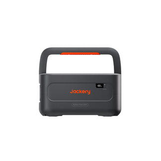
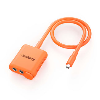












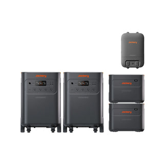
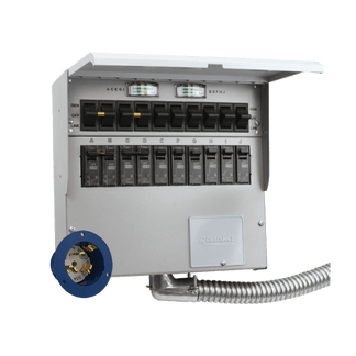


Battery grounding and neutral bonding are different parts of a LiFePO4 home backup system. Grounding provides a protective path for equipment and enclosures, while neutral bonding establishes a controlled neutral-to-ground relationship. The safe arrangement depends on the complete source-to-load topology, including the inverter, transfer equipment, panel, loads, and existing service bond. Do not choose a bond location based on a battery label, inverter display, receptacle reading, or symptom.
Grounding and Neutral Bonding Are Different Safety Functions
The first step in battery grounding is to distinguish the protective equipment path from the neutral-bonding question. Both belong in the design review, but they address different safety concerns.
What Battery Grounding Does
Battery grounding concerns the protective path connected to exposed conductive parts, such as a battery or inverter enclosure, transfer equipment, and associated panels. That path should be permanent and continuous for the relevant circuits, equipment, and enclosures—not an optional accessory. Review the equipment-grounding conductor and its connections through the complete backup path rather than stopping at the battery cells. The OSHA grounding guidance supports this general continuous-path principle.
LiFePO4 chemistry does not determine the grounding method by itself. The enclosure, inverter output, connection method, transfer equipment, panel arrangement, and applicable documentation matter more than the chemistry. Grounding in a home battery backup setup is therefore a system question, not a battery-only question.

What Neutral Bonding Does
Neutral bonding addresses the controlled connection between the grounded circuit conductor, commonly called the neutral, and grounding or bonded equipment at a designated point in the system. It is separate from bonding exposed metal. In plain language, grounding and bonding serve different functions in the fault-protection design, as explained in this technical grounding and bonding overview. That overview does not, by itself, establish a complete home-backup grounding scheme.
The source arrangement, neutral switching or continuity, transfer equipment, and existing service bond determine how this relationship is evaluated. Where an additional connection is not permitted, an extra neutral-to-ground connection can place normal neutral current on equipment-grounding paths. Do not add, remove, or move a bond to resolve an unexplained trip or reading unless the documented design and adopted code clearly permit it. The NEC-based discussion of separately derived systems provides background, not a universal method for every LiFePO4 backup topology.

Map the Bonding Question to the Backup Configuration
The correct neutral-bonding analysis changes with the source path. Identify the normal source, backup source, transfer boundary, neutral behavior, panel arrangement, and equipment-grounding path before drawing a conclusion. A battery/inverter output may be a separately derived source when it has no direct electrical connection—including a solidly connected grounded conductor—to another source’s circuit conductors. The exact classification still depends on the equipment documentation and adopted local code.
| Configuration | Decisive facts to identify | Safe next action |
|---|---|---|
| Inverter-backed standby | Whether the backup output is isolated from utility conductors and how the inverter and transfer equipment handle the neutral | Compare the one-line diagram with the current manuals; do not infer the bond arrangement from “standby” or “expandable” labels |
| Whole-home or selected-circuit | Which loads and panels remain utility-connected, where transfer occurs, and whether the neutral is continuous or handled differently | Review the actual panel boundaries and transfer documentation; do not apply a whole-home assumption to a selected-circuit subpanel |
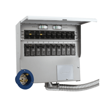
| Portable or add-on battery | Whether the connection is receptacle-fed or panel-connected, how the enclosure is grounded, and how the existing service bond interacts with the connection | Treat the listed connection method and exact manual as controlling; a grounding adapter or accessory alone does not validate the complete system |
Inverter-Backed Standby Systems
First, determine whether the inverter backup output is electrically isolated from the utility source and how the grounded conductor is handled during backup. The one-line diagram should identify the normal source, backup source, transfer points, equipment-grounding conductors, and designated bonding arrangement. Transfer equipment and the neutral connection determine the classification question—not the product terms “standby,” “expandable,” or “whole-home.”
If the documentation does not clearly show the source relationship and neutral behavior, the answer is unresolved. Do not select a bond location based on the inverter’s operating mode or an observed symptom.
Whole-Home and Selected-Circuit Backup
Whole-home and selected-circuit systems can route sources, neutrals, equipment-grounding conductors, and loads through different panels and transfer equipment. A whole-home installation may have a different source-to-load path than a selected-circuit subpanel, where some loads remain utility-connected. The neutral may be switched or continuous, depending on the design.
Use the actual diagram and panel boundaries rather than a general rule borrowed from another installation. The transfer-equipment background helps explain why topology and neutral behavior matter, but it does not determine the permitted bonding arrangement for a specific battery system. If you are researching transfer equipment, treat that article as background only, not as installation evidence.
Portable or Add-On Battery Systems
A receptacle-fed or listed portable connection is not automatically equivalent to a permanently connected backup source. Portable, expandable, and add-on labels do not establish whether the output can connect to a home panel or how its neutral behaves.
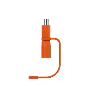
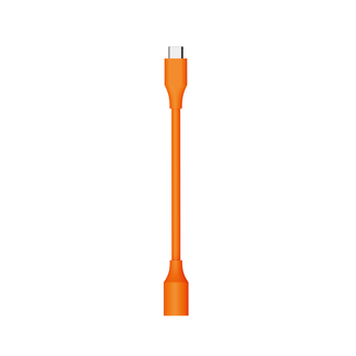
For an add-on panel connection, evaluate the existing service bond, panel layout, transfer method, enclosure grounding, and manufacturer-approved connection method together. A grounding adapter or accessory by itself cannot validate the complete system. If the proposed connection is not clearly covered by the current equipment instructions and diagram, pause before installation.
Use a Verification-and-Stop Path Before Installation or Troubleshooting
Start with the documents and a noninvasive path map, not a wiring change. If you cannot safely confirm the designated bond, neutral behavior, or continuous equipment-grounding path, stop treating the setup as verified and arrange a qualified electrical review.
Verify the Documented Path Before Changing Anything
- Collect the current battery and inverter manuals, transfer-equipment instructions, panel or one-line diagram, and available installer, permit, or inspection documentation.
- Map the normal source, backup source, neutral conductors, equipment-grounding conductors, enclosures, transfer points, and existing service bond without opening energized equipment.
- Compare that map with the documented permitted connection and bonding arrangement. If the documents conflict, do not assume the bond location; obtain a review.
This documentation-first process helps distinguish a real system-design question from an assumption based on a product name. It does not authorize live testing, panel access, or wiring changes.
Stop on Symptoms or an Unclear Bond
Treat these conditions as stop signals, not as instructions for adding a new bond:
- Nuisance trips or neutral-related alarms
- Tingling or energized metal
- Heat, buzzing, or unusual equipment behavior
- Unexpected inverter behavior or unusual voltage readings
- Missing, conflicting, or unclear diagrams
A symptom can result from more than a bonding issue, including an open conductor, incompatible transfer equipment, overload, equipment fault, or measurement error. Stop using the uncertain arrangement or de-energize it as appropriate, then arrange a qualified review. Do not add, remove, bypass, or relocate a neutral-ground connection to make the symptom disappear unless the documented design and adopted code clearly permit it.
Get a Qualified Electrical Review for Panel-Connected Systems
Use a qualified electrician or code-compliant installer for hardwired, whole-home, selected-circuit, or other panel-connected systems when the topology, neutral switching, bond status, or conductor identification is uncertain. Local permitting or inspection requirements may also affect the installation, depending on the jurisdiction.
The decision boundary is concrete: if the documented design does not identify the permitted connection, neutral behavior, and continuous equipment-grounding path, do not proceed on an assumption. Gather the equipment documents and arrange a qualified electrical review before installation or troubleshooting.
Frequently Asked Questions
These answers apply the same topology-first approach to common planning questions.
Does a LiFePO4 home backup system need both grounding and neutral bonding?
A system may involve both functions, but they are not interchangeable. Grounding addresses the protective equipment path, while neutral bonding addresses the designated neutral-to-ground relationship. The inverter, transfer equipment, panel, and service arrangement determine how each is implemented.
Where should the neutral-ground bond be in a home battery backup system?
Use the current inverter and transfer-equipment diagrams together with the existing service arrangement to identify the documented bonding point. Do not select a location from a receptacle reading, inverter display, product label, or troubleshooting symptom.
When should I call an electrician about battery grounding or neutral bonding?
Call for a qualified review when a system is hardwired or panel-connected and its topology, neutral behavior, bond status, or conductor identification is unclear. Also stop and seek a review for nuisance trips, unusual voltage behavior, tingling or energized metal, heat, buzzing, or unexpected inverter behavior.


